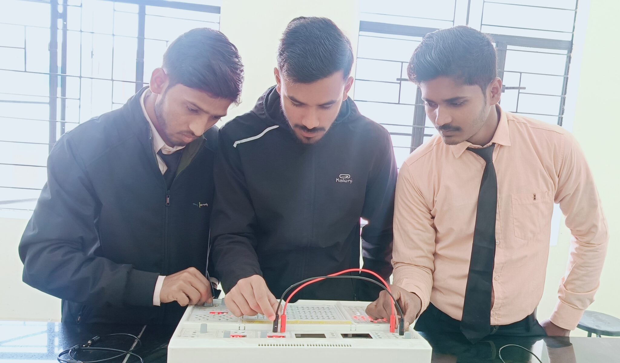
Digital Electronics Laboratory
Step into the Digital Electronics Laboratory, a space where innovation meets implementation, and binary logic transforms into real-world applications. This dedicated facility within our B.Tech curriculum is designed to provide students with hands-on experience in the dynamic field of digital electronics, equipping them with the skills to design, simulate, and implement digital circuits.
Prof. In-Charge
Mr. Bijay Kumar
Assistant Professor
Department of Electrical Engineering


Laboratory Infrastructure
- State-of-the-Art FPGA Boards: The laboratory is equipped with modern Field-Programmable Gate Array (FPGA) boards, enabling students to implement complex digital circuits and gain insight into the world of programmable logic.
- Digital Oscilloscopes and Logic Analyzers: High-performance digital oscilloscopes and logic analyzers facilitate the measurement and analysis of digital signals, providing students with tools for debugging and optimizing their designs.
- Simulation Software: Complementing practical exercises, the lab integrates simulation software that allows students to design and simulate digital circuits before implementation, ensuring a thorough understanding of circuit behavior.
List of Experiments
- Design an Ex-OR gate using a minimum number of 2 input NAND gates IC 7400.
- Implementation of a Boolean function F = A.B.C.D.E using AND gates IC 7408.
- Design and test a Half Adder and Full adder using a minimum number of NAND gates IC 7400 and modify it to the subtractor.
- Design and testing of 1:8 Demultiplexer using IC 7404, IC 7408, and IC 7432.
- Design and testing of 8:1 multiplexer using IC 7404, IC 7408, and IC 7432.
- Design and realization of 4-bit magnitude comparator using IC 7485.
- Design and realization of Binary to Gray code converter using IC 7486.
- Design and realization of Gray to Binary code converter using IC 7486.
- Design and realization of 4:2 line encoder using IC 7432.
- Design a 3-stage synchronous counter using JK F/F to count up and down from 0 to 7 and from 7 to 0.